📖 How-To Guide: Creating a Virtual Installation Rendering (VIR) with EZSign.Tools
Overview
In this guide, you'll learn how to use the VIR (Virtual Installation Rendering) tool inside the EZSign.Tools platform to create a photorealistic sign mockup on a real-world building photo. You'll walk through launching the tool, loading your brand asset and location photo, calibrating real-world scale, defining the wall's perspective, placing and detailing your sign, and finally generating a client-ready presentation proof.
📋 Prerequisites
Before you begin, make sure you have:
- An active EZSign.Tools account with an Unlocked Premium subscription (or access to the Free Beta tier)
- A brand asset / CAD file of your sign (e.g.,
.gltfor.glbformat) - A location photo of the building or storefront where the sign will be visualized
- The actual real-world measurement (in inches) of a known reference point on the building (for scale calibration)
- (Optional) A custom
.svgpresentation template if you want branded proof documents
1. Launch the VIR Tool
Start by opening the VIR application from the main EZSign Tools dashboard.
- Navigate to the EZSign Tools & Applications dashboard.
- Confirm your subscription status — tools under Premium Suite will display a green 🔓 Unlocked badge if your membership is active.
- Click Launch VIR (Full) to open the tool in a new tab.
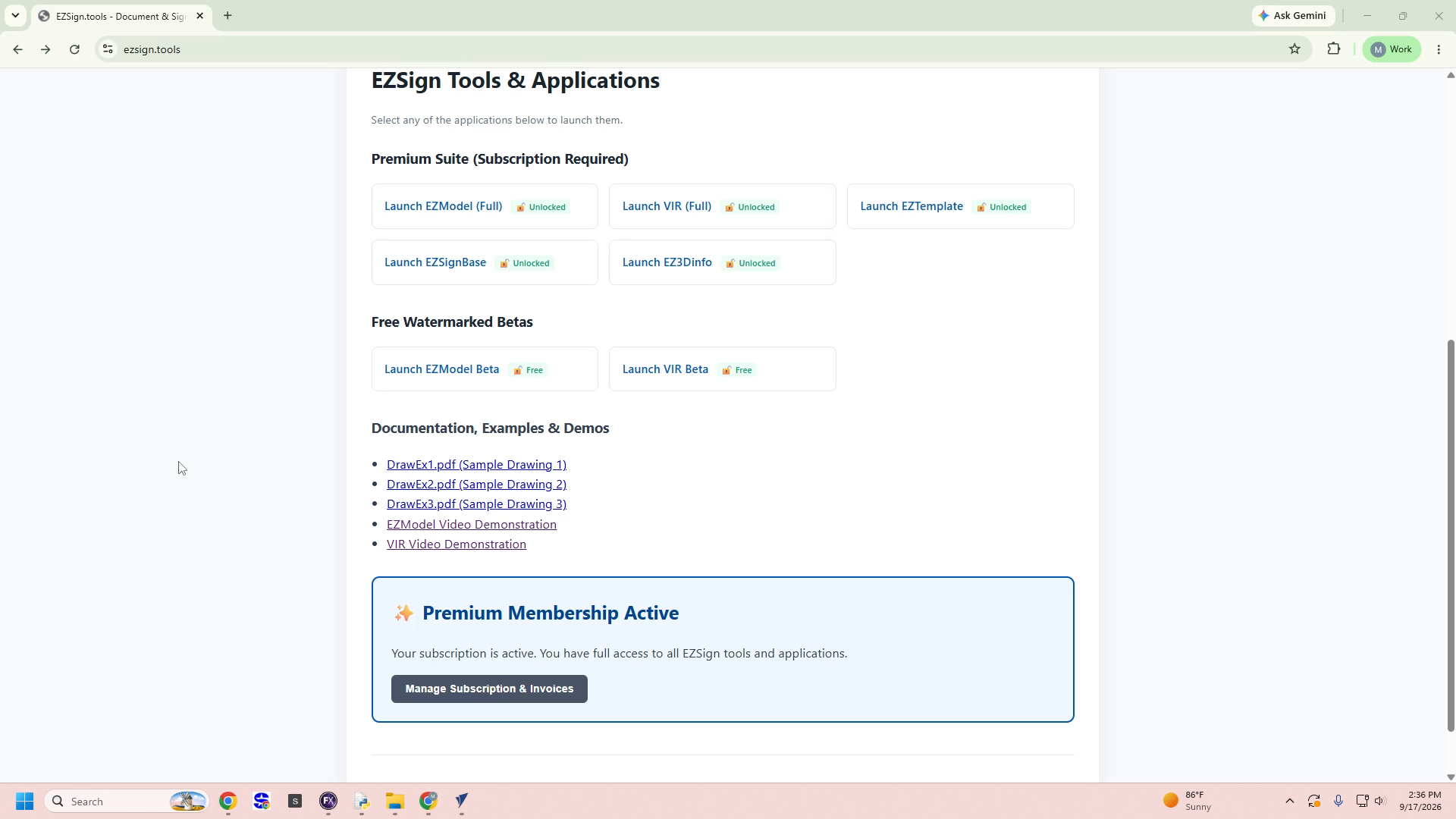
💡 Tip: If you don't have an active subscription, you can still test the workflow using Launch VIR Beta, which produces a watermarked preview.
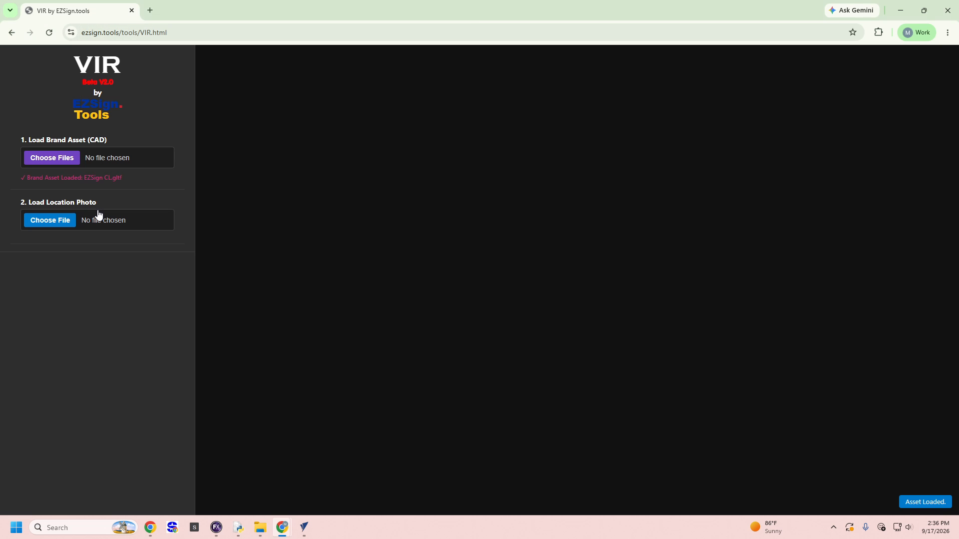
✅ Result: The VIR workspace opens, displaying an empty canvas and a prompt to "Load Brand Asset and Location Photo to begin."
2. Load Your Brand Asset (CAD File)
The brand asset is the 3D sign model that will be rendered onto your location photo.
- In the left sidebar, locate 1. Load Brand Asset (CAD).
- Click the purple Choose Files button.
- In the Open file dialog, navigate to your assets folder (e.g.,
EZSign-Tools > Graphic assets). - Select your sign file — supported formats include
.gltf,.glb,.stl,.obj, and.mtl. - Click Open to confirm the selection.

✅ Result: A confirmation message appears in red text: ✓ Brand Asset Loaded: EZSign CL.gltf.
3. Upload the Location Photo
Next, upload the real-world photo where the sign will be virtually placed.
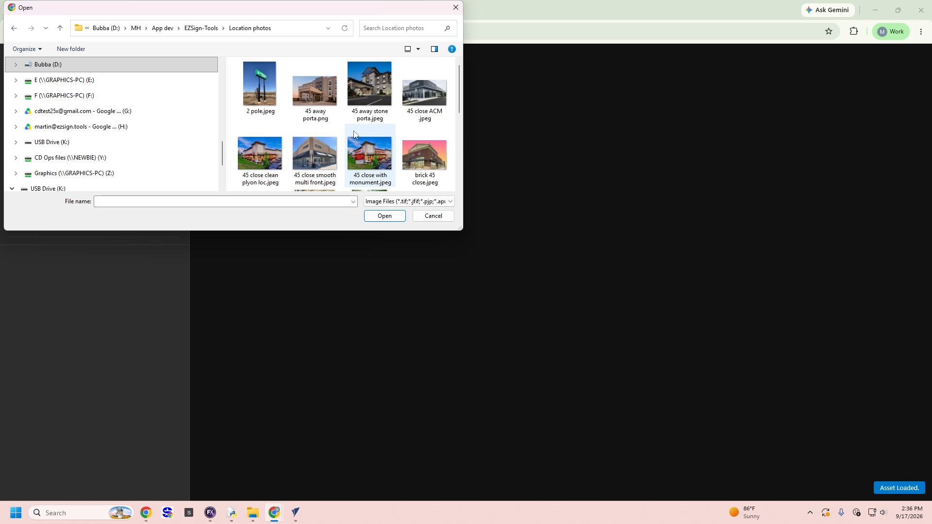
- Locate 2. Load Location Photo (or Change Location Photo) in the sidebar.
- Click the blue Choose File button.
- Browse to your photo folder (e.g.,
EZSign-Tools > Location photos). - Select the desired image thumbnail — such as
45 close with monument.jpeg. - Click Open to load the photo into the canvas.
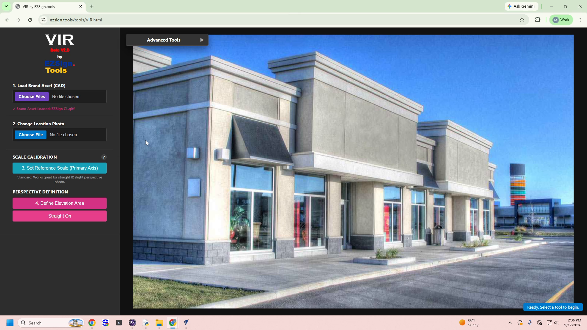
✅ Result: The building photo populates the main canvas, and the Scale Calibration and Perspective Definition tools become available.
4. Calibrate the Scale
Scale calibration establishes a pixel-to-inch ratio so the sign renders at the correct real-world size.
- Click 3. Set Reference Scale (Primary Axis) (teal button).
- Click the first point on a known measurement in the photo (e.g., top of a wall edge).
- Click the second point to finish the reference line.
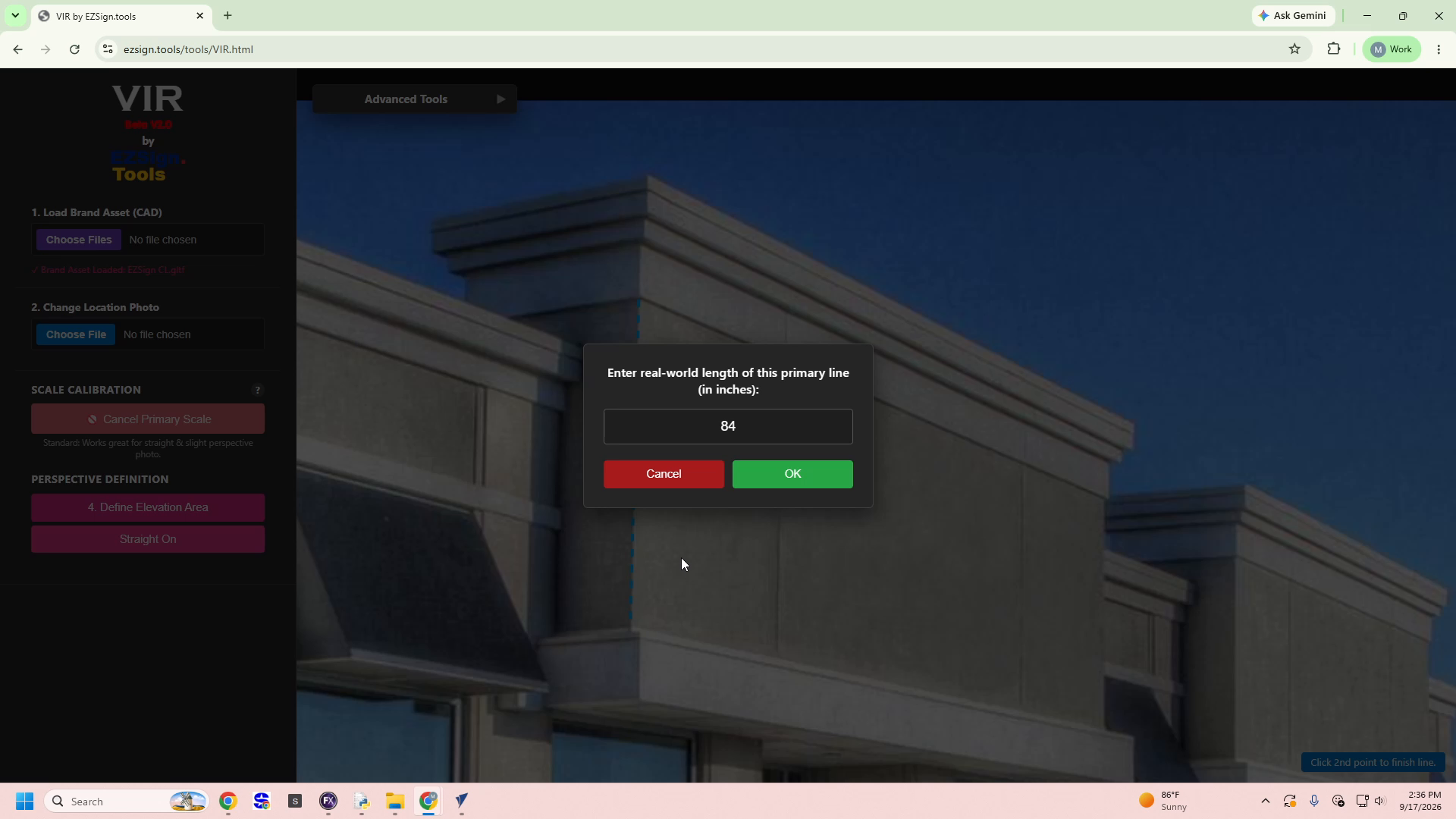
- In the dialog "Enter real-world length of this primary line (in inches):", type the actual measurement — for example
84. - Click the green OK button to confirm.
- (Optional) Click Edit 2nd Axis Scale to calibrate a second reference axis for improved accuracy on angled photos.
💡 Tip: Use the Standard mode for straight-on or slight-perspective photos. For more complex angles, complete both primary and secondary axis calibration.
✅ Result: The sidebar status updates to Dual-Axis Ground Truth Locked (X & Y), confirming the scale is set.
5. Define the Elevation Area (Perspective)
This step maps the wall surface where your sign will be placed, ensuring correct perspective alignment.
- Click 4. Define Elevation Area (pink/magenta button).
- Select a perspective mode — click Straight On for flat-facing walls.
- Click each corner of the wall/elevation area in sequence as prompted:
- Click Top-Right corner
- Click Bottom-Right corner
- Click Bottom-Left corner
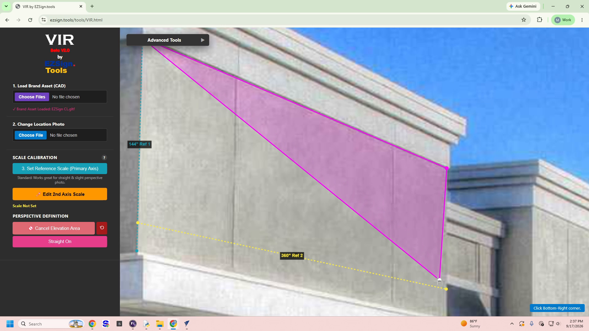
- Continue until all four corners are placed, forming a complete magenta quadrilateral over the wall.
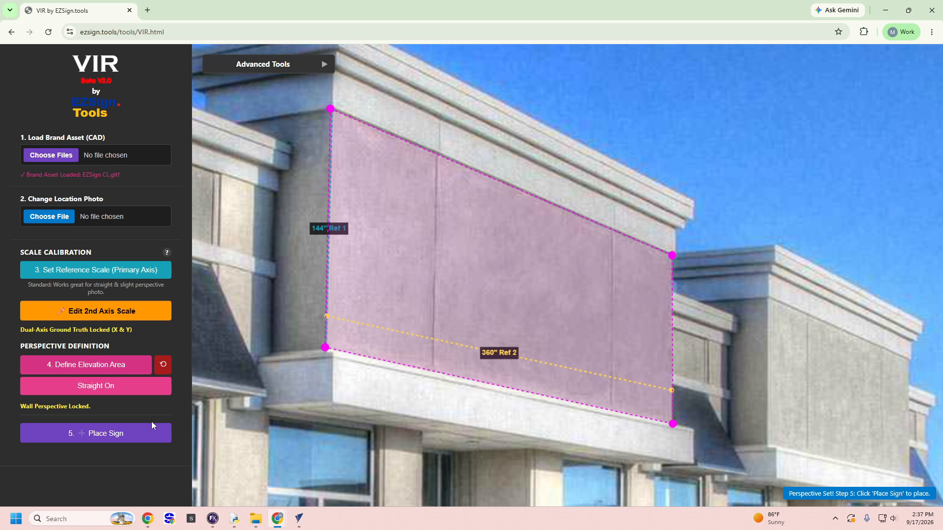
✅ Result: The status text updates to Wall Perspective Locked., and a notification confirms: "Perspective Set! Step 5: Click 'Place Sign' to place."
6. Set Sign Dimensions and Place the Sign
With scale and perspective locked, you're ready to size and position your sign.
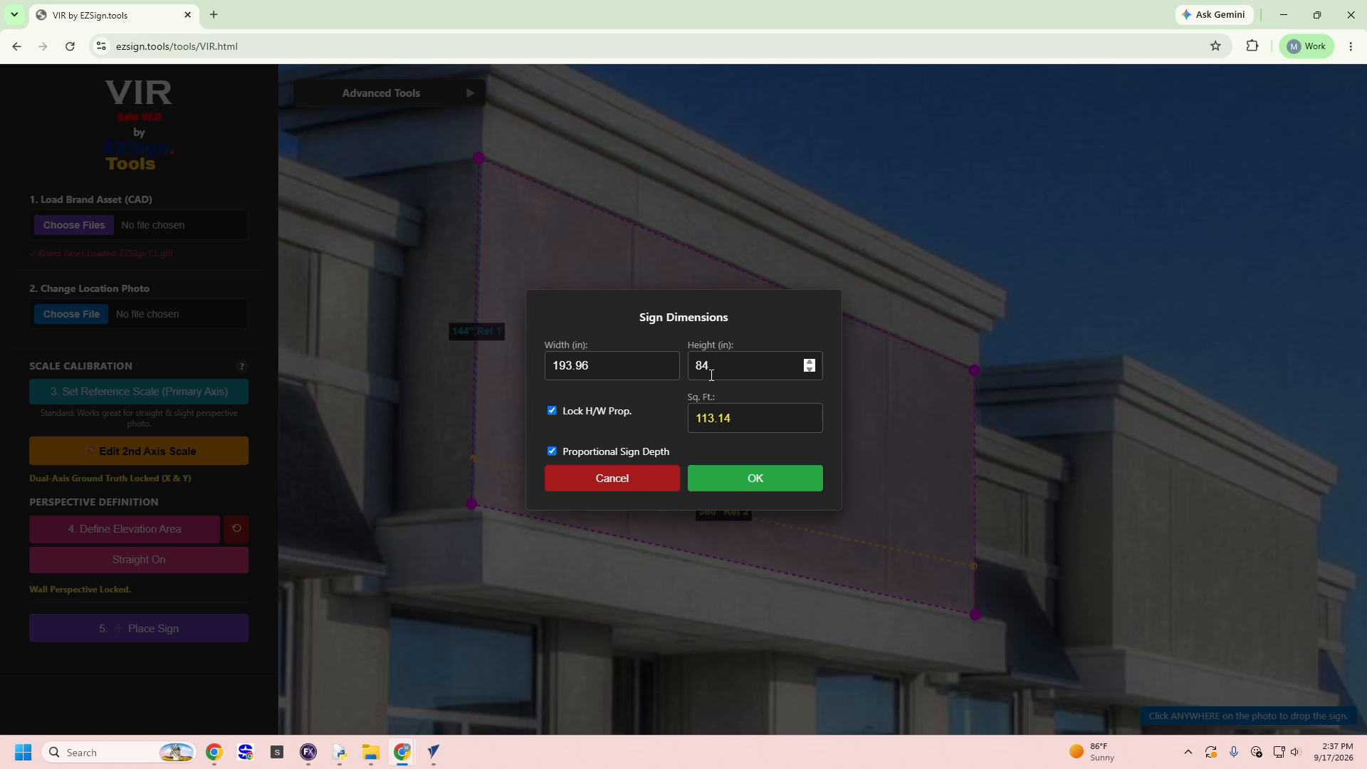
- Click 5. + Place Sign to open the Sign Dimensions dialog.
- Enter the Width (in) and Height (in) values — for example,
193.96and84. - Check Lock H/W Prop. to maintain proportional scaling, and Proportional Sign Depth if applicable.
- Review the auto-calculated Sq. Ft. value (e.g.,
113.14). - Click the green OK button to confirm dimensions.
- Click anywhere on the photo to drop the sign onto the calibrated wall surface.
- Click on the sign and use arrow keys to move object along surface.
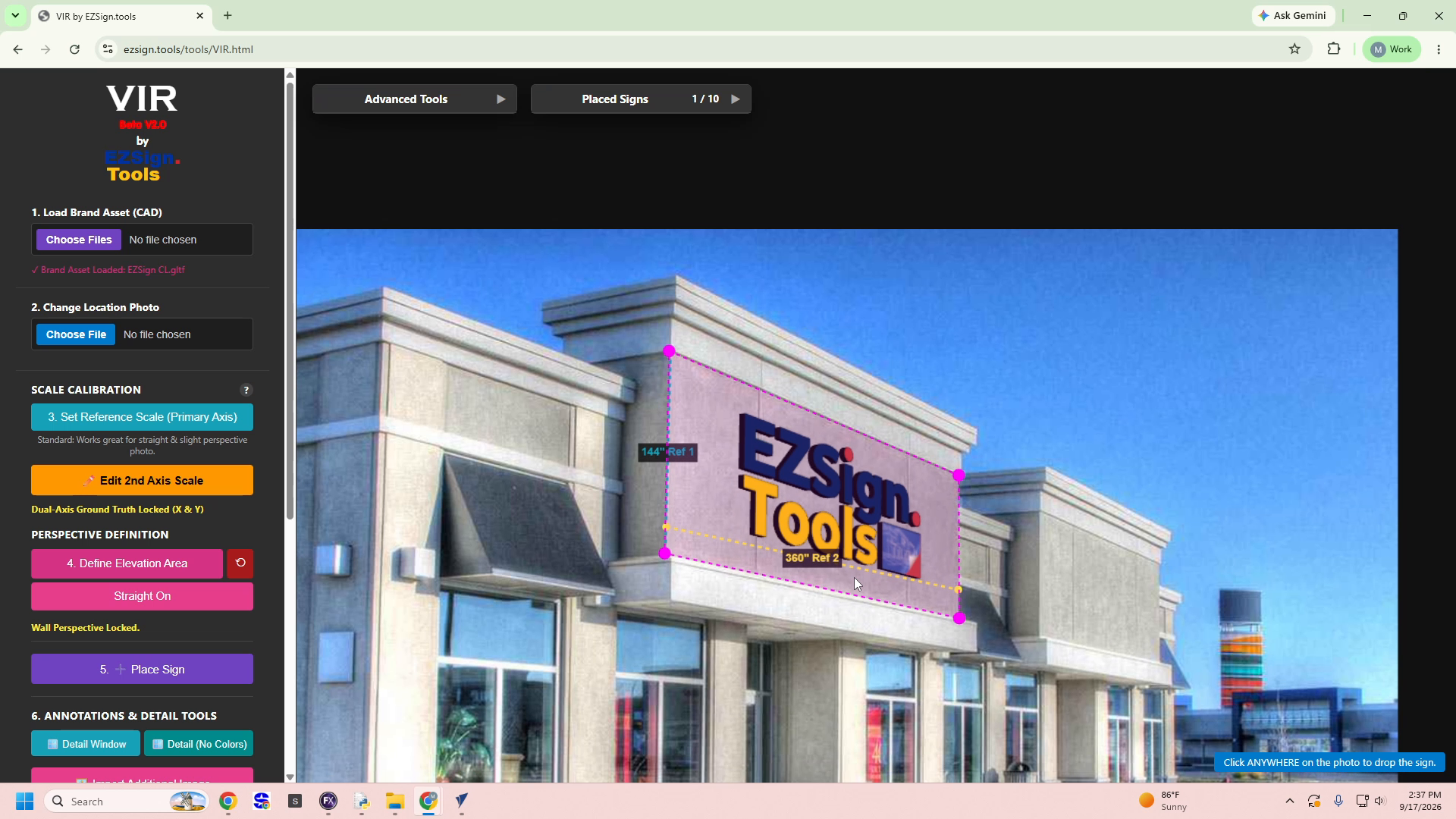
✅ Result: The sign is rendered onto the storefront photo in correct scale and perspective, tracked as 1 / 10 in the Placed Signs counter.
7. Add Annotation & Detail Windows
Detail windows add technical specifications directly onto your rendering — useful for client proofs and fabrication reference.
- Scroll to 6. ANNOTATIONS & DETAIL TOOLS in the sidebar.
- Click Detail Window to generate a full specification card, or Detail (No Colors) for a simplified version.
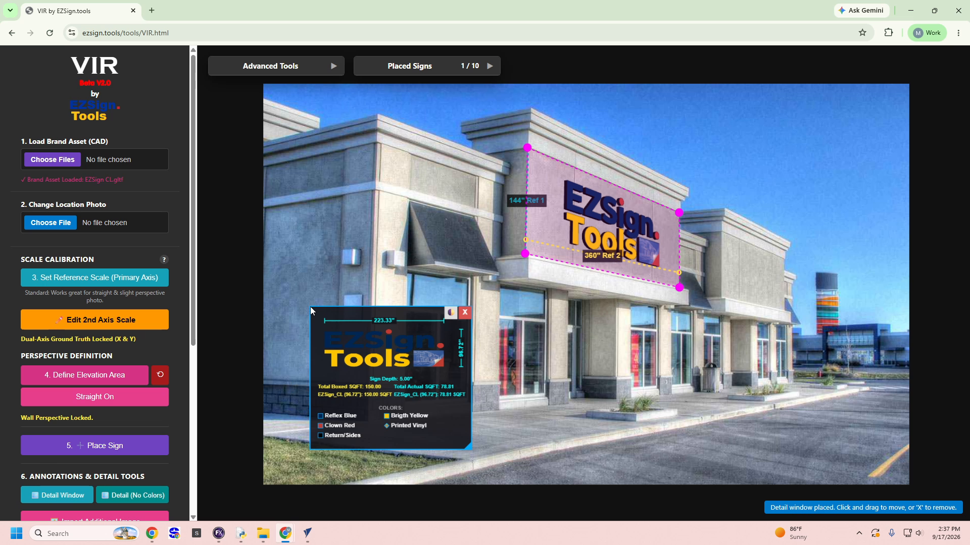
- Click and drag the detail window to reposition it on the canvas.
- Review the auto-generated specs, including:
- Width / Height dimensions
- Sign Depth
- Total Boxed SQFT vs. Total Actual SQFT
- Colors legend (e.g., Reflex Blue, Bright Yellow, Clown Red, Printed Vinyl, Return/Sides)
- Click the X button on the window if you need to remove it.
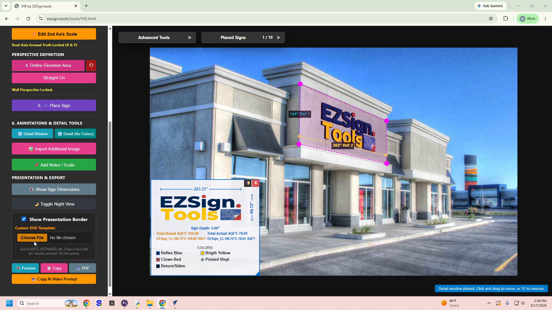
✅ Result: A movable, closable specification card is overlaid on the rendering, confirmed by the notification "Detail window placed. Click and drag to move, or 'X' to remove."
8. Apply a Custom SVG Presentation Template (Optional)
For branded client proofs, you can upload a custom SVG template with dynamic text fields.
- Scroll to the PRESENTATION & EXPORT section.
- Click Choose File next to Custom SVG Template.
- In the file dialog, select your
.svgfile (must include arender_windowrect and optional placeholders like{CLIENT},{ESTIMATE}). - Click Open to upload the template.
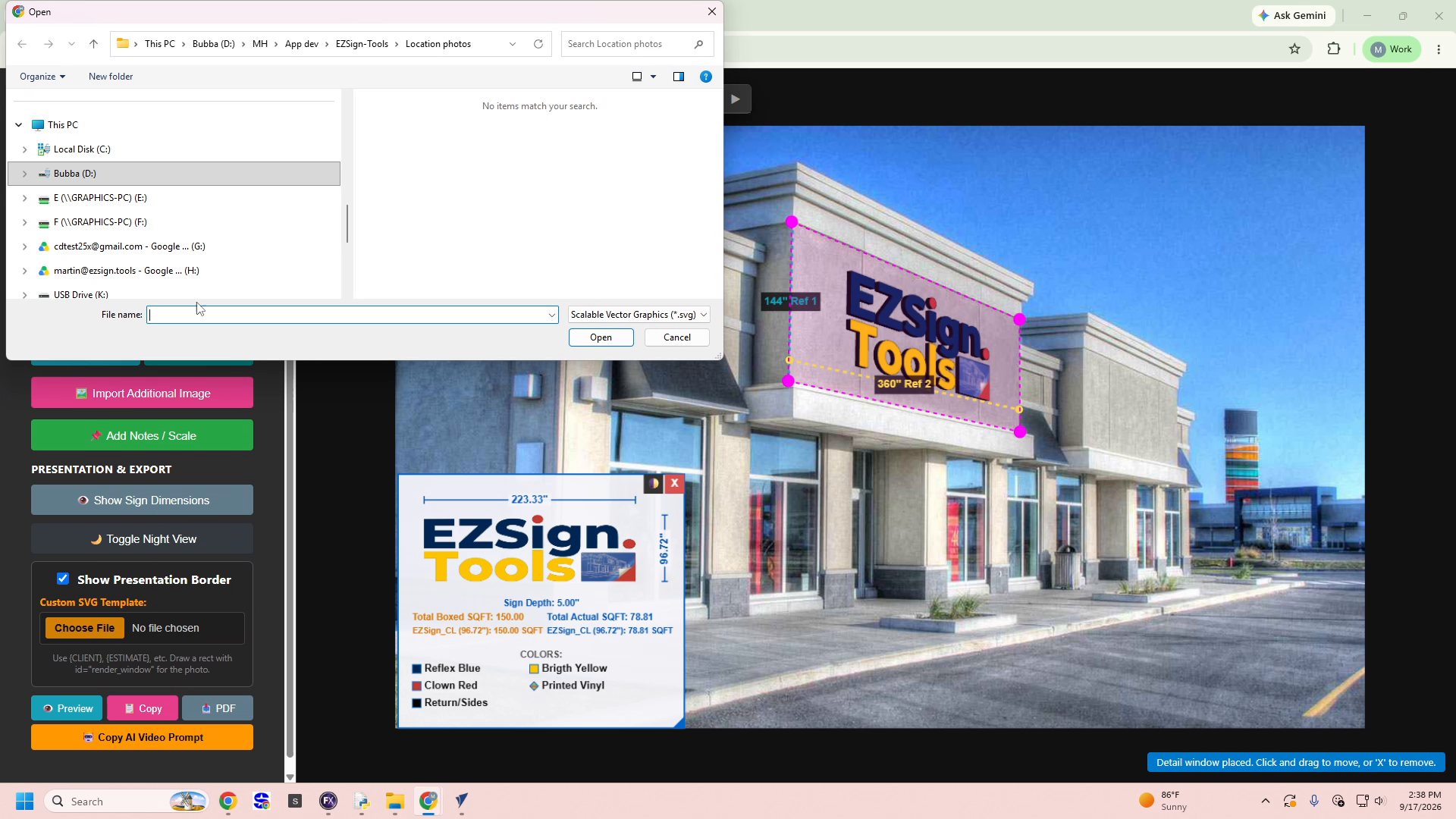
- Once loaded, fill in the Dynamic SVG Fields detected from your template, such as:
CLIENT→ e.g.,DemoESTIMATE→ e.g.,123454DATE→ auto-populated or manually enteredREV→ enter revision number if applicable
✅ Result: The sidebar confirms ✓ SVG Template Loaded (4 fields detected), and your entered values populate the presentation overlay in real time.
9. Generate and Review the Presentation Preview
Finish by generating a client-ready proof document with all your sign details and photo mockup.
- Optionally toggle Show Sign Dimensions, Toggle Night View, or Show Presentation Border to customize the final output.
- Click the Preview button to render a high-resolution proof.
- Wait for the "Rendering High-Res Preview..." spinner to complete.
- Review the Presentation Preview modal, which includes:
- Client, Estimate, Date, and Revision header fields
- The sign mockup overlaid on the location photo
- Full dimension and color specifications
- Standard approval and disclaimer footer text
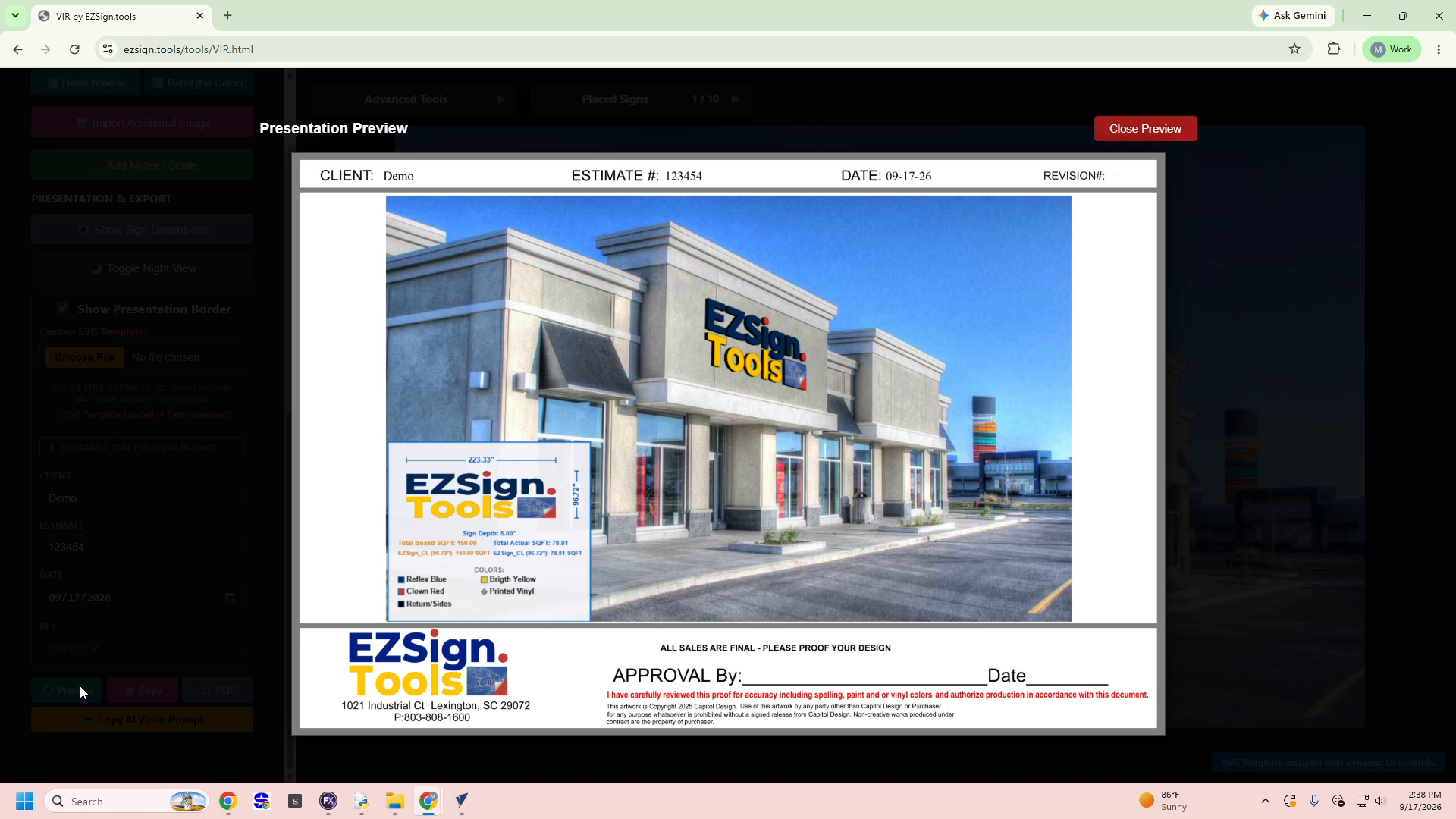
- Use the Copy, PDF, or Copy AI Video Prompt buttons to export or share your finished proof.
- Click Close Preview to return to the editing canvas.
✅ Result: A polished, client-facing presentation proof is generated — combining your branded sign mockup with accurate real-world measurements and specifications, ready for approval or fabrication.
🎉 What's Next
You've now completed a full VIR workflow — from loading a brand asset and location photo, through scale calibration and perspective locking, to placing, detailing, and exporting a client-ready sign presentation.
From here, you can:
- Repeat Steps 6–7 to place additional signs (up to
10per project) on the same photo. - Experiment with different Custom SVG Templates for varied branding needs.
- Explore other tools in the Premium Suite, such as EZModel, EZTemplate, or EZ3Dinfo, to expand your design workflow.
- Visit Manage Subscription & Invoices on the main dashboard to review your billing details or upgrade your plan.
💡 Final Tip: Save your project regularly and revisit the Placed Signs counter to keep track of multiple sign placements within a single rendering.